本课程指导学员使用VHDL驱动ADC与UART,结合C#开发Windows上位机,从零构建FPGA USB示波器,掌握数据采集与软硬件联合调试的工程技能。
原始标题:Build an FPGA Oscilloscope with VHDL and C#
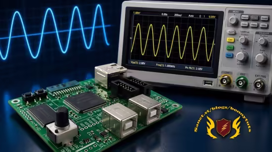
该视频课程通过硬核的项目驱动教学,指导具备基础 VHDL 知识的学员从零开始构建一个基于 FPGA 的 USB 示波器系统。课程全面打通软硬件联合开发链路:底层使用 VHDL 语言编写 SPI 协议以驱动板载 ADC 进行实时信号采集,并自主设计 UART 发送逻辑通过 USB 虚拟串口将数据流传输至 PC;上层则指导学员使用 C# 语言开发 Windows 桌面应用程序,实现高速串行端口的数据解析与高帧率实时动态波形绘制,从而帮助嵌入式开发者和学生彻底掌握工业级数据采集、底层总线通信及上位机联调的核心工程技能。
Last updated 6/2026
Created by L Athukorala
MP4 | Video: h264, 1920×1080 | Audio: AAC, 44.1 KHz, 2 Ch
Level: Intermediate | Genre: eLearning | Language: English | Duration: 9 Lectures ( 1h 51m ) | Size: 1.7 GB
Design an FPGA-based USB oscilloscope from scratch using VHDL and a C# desktop application
What you’ll learn
⚡ Learn how to interface an FPGA with an ADC using SPI in VHDL.
⚡ Design and implement a simple UART transmitter in VHDL.
⚡ Transfer real-time sample data from FPGA hardware to a PC over USB (Virtual Comm Port).
⚡ Develop a C# Windows application to receive and process serial data.
⚡ Create a real-time oscilloscope-style waveform display on the PC.
Requirements
❗ Must have a basic understanding of the VHDL language
❗ Understanding clocks, resets, and synchronous logic
❗ If you have completed an introductory VHDL course, you are well prepared for this material.
Description
In this hands-on FPGA course, you will learn how to build a simple USB-based PC oscilloscope from start to finish using VHDL and C#. The course uses theFPGA Explorer Development Board as the development platform.
The course begins by showing how to interface an FPGA with an on-board Analog-to-Digital Converter (ADC) using the SPI protocol. You will then design UART communication logic in VHDL to stream real-time ADC sample data from the FPGA to a PC through the development board’s USB-to-UART interface.
On the software side, you will develop a C# Windows desktop application capable of receiving serial data from the FPGA and displaying it as a live real-time waveform graph, creating a basic oscilloscope-style real time signal plotting interface.
This course is designed to provide practical experience with FPGA development and hardware/software integration while introducing several important embedded engineering concepts, including
✨ SPI communication in VHDL
✨ UART transmitter design
✨ Real-time data acquisition
✨ USB serial communication
✨ FPGA-to-PC interfacing
✨ C# serial port programming
✨ Real-time waveform plotting
While this project is intentionally simple and not a full-featured commercial oscilloscope, the concepts you will learn are extremely important and widely used in embedded systems and FPGA development. You will gain practical experience with FPGA design, serial communication, real-time data acquisition, and hardware/software integration.
By the end of the course, you will have a complete working project and a strong understanding of how FPGA hardware and PC software can work together to create real-time measurement and visualization systems.
Whether you are interested in FPGA development, digital design, embedded systems, or hardware/software integration, this project-based course will give you practical skills you can build upon for more advanced designs in the future.
Who this course is for
⭐ Students with basic VHDL knowledge looking to move beyond simple demos
⭐ Hobbyists and makers interested in FPGA projects
⭐ Engineers or embedded developers who want hands-on FPGA experience
⭐ Learners who want to build reusable skills for advanced FPGA projects
⭐ Anyone curious about low-level FPGA SPI and UART interfaces
百度网盘下载: